
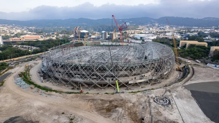
We have walked onto stadium sub-base projects that looked immaculate on handover day and failed within two seasons because the buried layer was never tested. On most of our larger artificial turf installations, the visible carpet is the part the owner inspects. The engineered substructure beneath it is the part that decides drainage, slope and shock attenuation. Our team treats that buried layer as the engineering deliverable, not a soil-moving subcontract.
Factory-direct sourcing changes the conversation. When the mill ships the roll and signs the sub-base spec on the same calendar, the contractor cannot blame the carpet for drainage failure. The framework below turns stadium substructure for artificial turf into a system you can spec, install and sign off on. It uses only quantitative thresholds drawn from peer guides and the field experience behind them.
Stadium Substructure: The Hidden Half of Turf
Once the turf is unrolled, the substructure disappears from view. That is the moment when the project becomes a hostage to the layer below. Walk a stadium three days after a 30-millimetre downpour and the scoreboard reads the verdict: ponding, soft patches, a cancelled fixture. The buried layer decides whether the field opens or stays shut.
Most stadium substructure for artificial turf guides open with a checklist of crushed stone, drainage pipe and compaction. That is the supply-side view. The buyer’s view is different: the design that survives ten years is the one where drainage, structural stability and shock absorption are planned together from the first borehole. Bolting those pieces on after the rain hits the site is the failure mode we see repeated.
We were called to a 7,000-seat municipal stadium after a Saturday match was cancelled for standing water at the centre circle. The drain pipes were present, the crushed-stone base was present, but the infill had migrated into the perforated backing during the first season. The corrective contract ran into six figures before the next fixture.
Our team treats the substructure as the engineering deliverable. The carpet is the visible product the client sees; the base is the part that ages out of sight. Spec the wrong depth, lift, slope or density and no amount of pile height or fibre shape will save the field.
Designing the Sub-Base as One Hydraulic and Structural System
Stadium substructure for artificial turf is one system with four jobs: carry load, shed water, finish flat and absorb impact. Each job has a measurable threshold. Each threshold lives inside a single design drawing, signed once, before any stone is tipped on site.
Geotechnical boreholes drive the whole plan. The standard bore depth for a stadium field is 10 to 15 feet, deep enough to identify clay seams, loam pockets, sand lenses or expansive soil layers. Where the bore shows heavy clay or high plasticity, lime or cement stabilisation is standard practice. Where it shows a high water table, the drainage design gets a separate line item before the stone arrives.
Topsoil stripping depth before sub-base placement is 12 to 24 inches, depending on the geotechnical report. The total build-up from the bottom of excavation to the top of finished turf is typically 12 to 20 inches in a sports field. That range is the budget for four separate layers stacked into one cross-section.
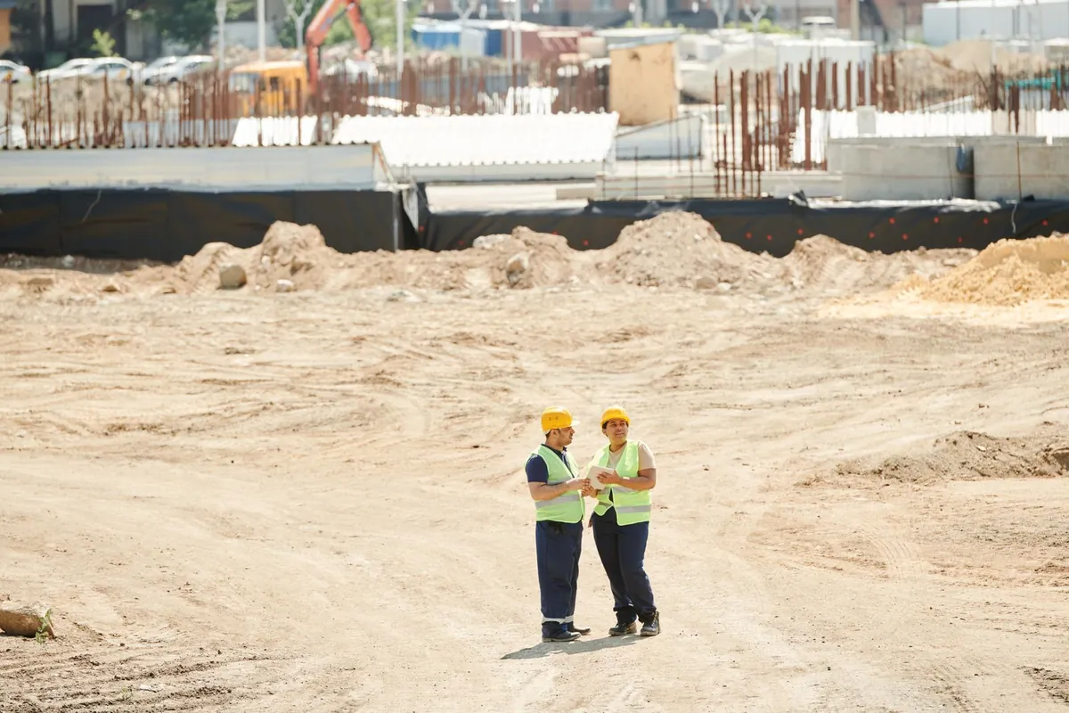
The four functions above the native subgrade each pick their own material.
Load-bearing capacity comes from the crushed-stone sub-base, compacted in lifts of 4 to 6 inches. The compaction target is 95 to 98 percent of Modified Proctor on engineered aggregate, with Class II or Class V recycled aggregate as the most common material. A typical sports construction floor is 95 percent; below that, settlement shows up within two seasons.
Drainage capacity comes from a perforated pipe network laid in clean stone, connected to an approved outlet such as a storm sewer, detention pond or bioswale. The pipe network is what makes the rest of the design work; without it, the crushed stone is just a sponge under the carpet.
Flatness comes from a 2 to 4 inch leveling course of finer aggregate or stone dust, finished by laser grading. The tolerance is conservative: grade deviations greater than 3/8 inch over a 10-foot span must be corrected at base acceptance. Corrections after the turf is laid are extremely costly.
Elasticity comes from a shock pad layer of closed-cell PE foam at 10 to 25 millimetres thick. Density is 30 to 50 kilograms per cubic metre, and the pad is laid between the leveling course and the carpet. The pad carries most of the head-impact attenuation; combined with infill, it provides 60 to 80 percent of the system’s measured shock performance.
| Функция | Material | Spec | Source |
|---|---|---|---|
| Load bearing | Class II / V crushed stone | 4–6 in lifts, 95–98% Modified Proctor | UDC Sports |
| Дренаж | Perforated pipe in clean stone | French 5–15 ft; slit 4–6 in; chip ASTM #57/#8 | UDC Sports |
| Flatness | Stone dust leveling course | 2–4 in, laser graded, ≤3/8 in over 10 ft | UDC Sports |
| Elasticity | Closed-cell PE foam shock pad | 10–25 mm, 30–50 kg/m³ | MightyGrass |
These four functions can be assembled in different combinations depending on rainfall, soil and budget. The four sub-base types below are pulled from peer guides.
| Sub-base type | Build | Best fit |
|---|---|---|
| Engineered aggregate base | Compacted crushed stone only | Standard sites, moderate rainfall, stable subgrade |
| Dynamic base | Crushed stone + angular aggregate + engineered interlayer | Sites with marginal soils or heavy use |
| Geo-textile sub-base | Separation fabric between subsoil and aggregate | Fine-grained or migrating subgrade |
| Permeable asphalt base | Porous asphalt over a stone reservoir | High rainfall sites needing flat fields with rapid drainage |
The four functions and four types are not interchangeable. Each combination sets different tolerances for compaction, slope and finish flatness. The next section narrows that decision to the drainage layer, where most B2B projects first fail.
Choosing a Drainage Layout That Survives Real Rainfall
A drainage layout is the one substructure decision you can test on the day of the storm. Pipe spacing, slope and outlet capacity are the three variables to lock before any stone is delivered. Get any one wrong and the rest cannot recover.
Three drainage families cover most stadium sites. French drains use perforated pipe in clean stone at 5 to 15 feet spacing across the field. Slit drains are narrow trenches 4 to 6 inches wide filled with coarse sand or gravel. Chip drains use a uniformly graded angular stone such as ASTM #57 or #8 as the drainage medium, with collector pipes at the perimeter.
French drains are the typical choice on moderate-rainfall sites with stable subgrade. Slit drains suit tight budgets and retrofit work where trench depth is constrained. Chip drains suit schools, municipal fields and lower-budget installations where the cost of perforated pipe is the deciding factor.
Every drainage layout must terminate at an approved outlet such as a storm sewer, detention pond or bioswale. Drainage water that daylights into a neighbouring property or sits in a holding pit is a liability, not a design. On heavy clay sites, add a French drain or channel drain as a secondary layer under the perimeter.
| Drainage system | Pipe / trench spacing | Aggregate | Best site | Cost band |
|---|---|---|---|---|
| French drain | Perforated pipe, 5–15 ft | Clean stone | Moderate rainfall, stable subgrade | Среднее |
| Slit drain | 4–6 in wide trench | Coarse sand or gravel | Tight budget or constrained trench | Низкое |
| Chip drain | No pipe, collector at perimeter | ASTM #57 or #8 angular stone | School or municipal lower budget | Low to mid |
| Secondary French or channel | Perimeter only | Clean stone | Heavy clay or low-lying site | Add-on |
Surface slope and crown profile work with the drainage pipe network, not instead of it. The standard field slope is 0.5 to 1 percent. A crown profile at 1 percent, roughly 1 inch per 8 feet toward both sidelines, is the typical geometry for a single-sport field. A flat field at 0.5 percent or less is preferred for multi-sport layouts, with the subsurface drainage carrying the design storm.
| Slope profile | Gradient | Типичное применение | Trade-off |
|---|---|---|---|
| Crown | ≈1% (≈1 in / 8 ft) | Single-sport football field | Fast surface shedding, lateral ball roll on edges |
| Flat / plane | ≤0.5% | Multi-sport stadium | Level playing surface, stronger subsurface drain needed |
| High-rainfall surface | ≥1% surface | Tropical or storm-prone sites | Aggressive shedding, harder on lateral ball roll |
The buried pipe network must accept what the carpet passes through. A new synthetic turf backing typically drains at 20 to 50 inches per hour. If the subsurface drainage layout delivers less, standing water migrates upward through the perforated backing and pools on the surface. This hydraulic coupling is the single biggest source of post-handover complaints we see on stadium substructure for artificial turf projects.
Substructure Done Before the Turf Was Chosen?
Surfaces fail when the layers were never matched. Bring the turf spec in early. Buying direct from the maker usually lands 30–50% below like-for-like market pricing.
Tying Roll Width and Backing Permeability to the Base Plan
Roll width and backing permeability are the two carpet-side variables that decide whether the substructure plan survives the first storm. They are also the two variables a B2B buyer can fix at the factory before shipping.
Standard roll sizes of 2m × 25m, 4m × 25m and 5m × 25m give three coverage options per roll: 50, 100 and 125 square metres. The 2-metre roll is the most economical and suits small areas. The 4-metre roll is the default choice when site dimensions are uncertain, because it covers most installations with the widest supply. The 5-metre roll suits large spaces with almost no seams, at a higher price and heavier handling.
Custom no-seam sizes are available for full-pitch layouts where the seam is the weakest link. Specify the seam-free length at the RFQ stage, not after delivery.
| Roll size | Coverage per roll | Seams per typical pitch | Best fit |
|---|---|---|---|
| 2m × 25m | 50 sqm | Many | Small areas, narrow access |
| 4m × 25m | 100 sqm | Умеренное | Default for most stadium pitches |
| 5m × 25m | 125 sqm | Few | Large spaces, fewer seams |
| Custom no-seam | Per pitch | Отсутствует | Premium full-pitch layouts |
Backing options on standard rolls are PP+Net and PU. PP+Net is the standard drainage backing with predictable perforation rate. PU is the higher-strength option, easier to heat-weld at seams. Both backings drain at 20 to 50 inches per hour when freshly perforated, setting the lower bound for the subsurface drainage design.
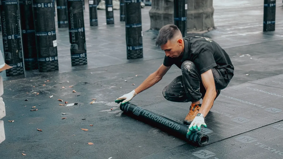
Seam planning starts with the base drawing. Place every seam on the highest-permeability section of the base, never on a low spot that the laser grader missed. The seam is where the carpet’s perforation rate drops to near zero; if it sits over a drainage dead zone, the rain will find it first.
Shock pad selection is the second carpet-side decision that ties to the base. Standard foam pads run 10 to 25 millimetres thick at 30 to 50 kilograms per cubic metre density. Standard rolls are 1.5m × 40–50m, covering 60 to 80 square metres per roll. The pad contributes 60 to 80 percent of the system’s measured shock attenuation together with the infill, so a thicker pad can offset a stiffer base.

A correctly specced pad and a correctly specced backing make the substructure design repeatable across sites. That repeatability is what B2B buyers pay for: every stadium gets the same hydraulic floor, and the only variable left is the infill depth at handover.
Locking the Base With a B2B Acceptance Checklist
Locking the base is a paperwork exercise, not a goodwill exercise. The base acceptance report is the only document that ties the contractor’s work to performance for the next decade. Five items must be on it, signed before any roll is unloaded.
The five items are surface flatness, slope, compaction, drainage flow and infill depth. Each has a number, each number has a source. The list below is the working draft we hand to the contractor at the kick-off meeting; the signed copy goes into the project file before the carpet is loaded.
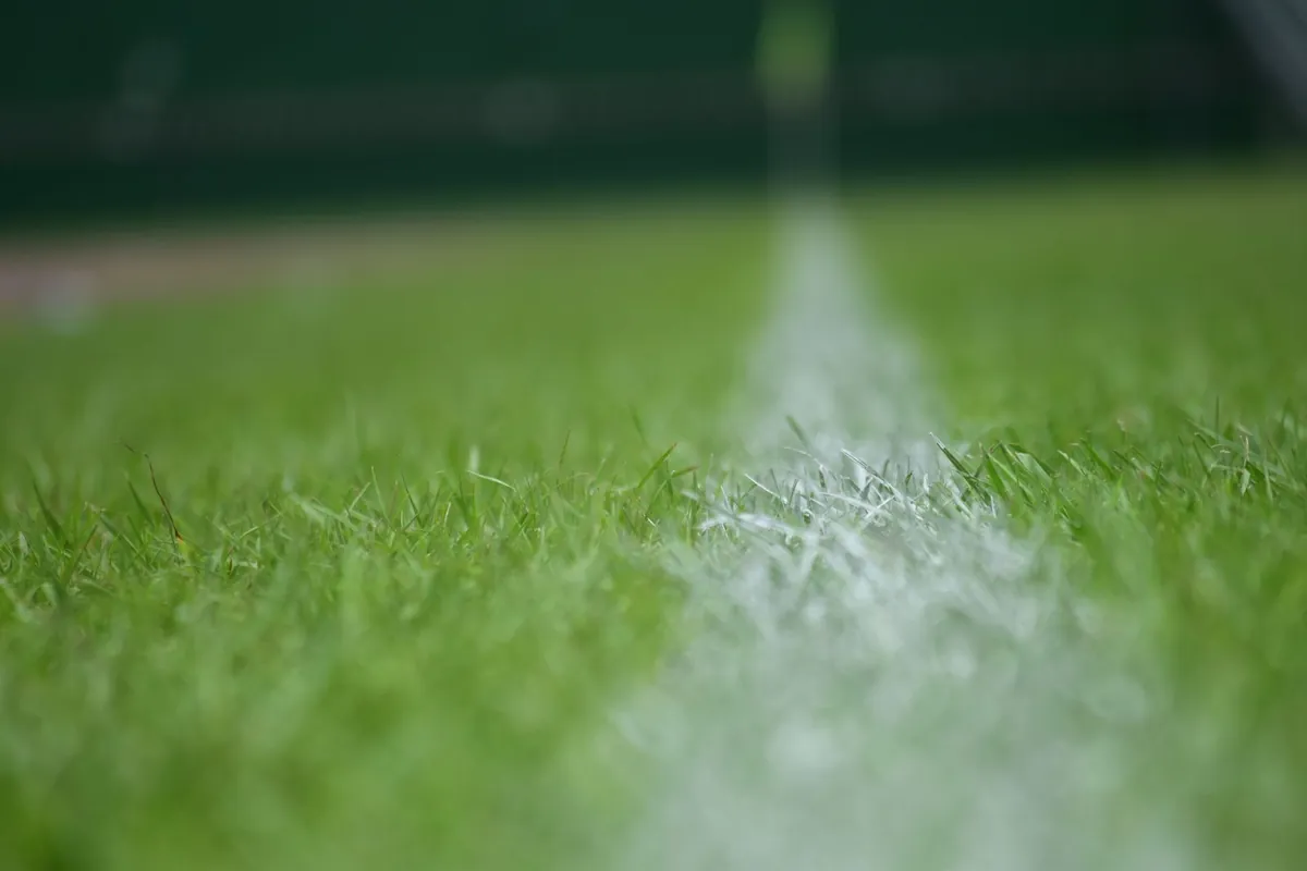
We attended a handover meeting at a 4,000-seat stadium where the contractor’s report carried only the compaction line. The slope was not measured, the flatness was eyeballed, and no drainage test had been run. The contractor left with a punch list longer than the original scope.
Surface flatness tolerance is conservative: deviations greater than 3/8 inch over a 10-foot span must be corrected at this stage. Slope must be measured against the design profile. Compaction must reach the Modified Proctor target specified in the design package, with the test report attached.
Shock attenuation at the finished field is the next number to lock. Independent testing on a finished system should keep surface hardness below the recommended limit measured with the F355 missile A device. The hard upper bound is the ASTM 1936 maximum. Above that bound, head-injury risk rises sharply.
After handover, infill depth becomes the routine test. Measure it monthly at 20 locations using a fire-proofing depth gauge, with extra attention to inlays, painted areas, seams and high-use zones. A reading that drifts more than 5 millimetres below spec is the early signal of compaction loss.
| Наименование | Threshold | If missed |
|---|---|---|
| Surface flatness | ≤3/8 in deviation over 10 ft | Re-grade before turf arrival |
| Slope profile | Match design (0.5–1% or crown 1%) | Re-laser grade the affected zone |
| Compaction | ≥95% Modified Proctor on engineered aggregate | Re-compact the failed lift, retest |
| Drainage flow | Outlet test passes design storm | Add collector pipe or surface inlet |
| Infill depth (post-handover) | Spec ±5 mm, 20 locations monthly | Top up infill, log the event |
With this checklist signed, the B2B buyer’s risk drops from ‘unknown field performance’ to ‘documented field performance’. The signed list is the artefact the next project manager reads on day one of the next job.
Sourcing Turf That Matches Your Engineered Sub-Base
The procurement side of stadium substructure for artificial turf closes when the carpet spec matches the base spec. Two backing families handle most engineered sub-base designs. PP+Net is the standard drainage backing with predictable perforation behaviour; PU is the higher-strength backing that heat-welds cleanly at seams. Both backings are available on the same production line, so the carpet spec follows the base spec rather than the other way round.
Roll dimensions can be matched to the base drawing at the RFQ stage. Standard widths are 2 metres, 4 metres and 5 metres at 25 metre lengths, giving 50, 100 and 125 square metres per roll. Custom no-seam sizes are also available for full-pitch layouts. Yarn colour, fibre shape, stitch density, pile height, backing composition and roll length are all adjustable on a production order.
Sample sizing follows the same flexibility. Standard 20 by 20 centimetre pieces ship in groups of three to four; customer pays shipping. DHL or FedEx typically clears the parcel in 4 to 6 days, remote destinations run 7 to 9 days, and custom samples add 10 to 15 days.
Send the base profile, shock pad thickness and carpet spec to your supplier in one envelope. The proposal comes back with one price band, one seam plan and one delivery window for the stadium substructure for artificial turf project.
Часто задаваемые вопросы
What is a typical stadium substructure depth?
A typical stadium substructure depth runs 12 to 20 inches from excavation bottom to finished turf top. That range covers the leveling course, shock pad and carpet layers stacked on the crushed-stone base.
How long does substructure preparation take before turf is laid?
Substructure preparation for a stadium typically takes 2 to 4 weeks depending on weather, drainage complexity and the compaction target. The base acceptance walk-through is the last step before any carpet is delivered.
Можно ли укладывать искусственный газон прямо на грунт?
No. Laying artificial turf directly on soil leads to settlement, drainage failure and seam movement within the first season. A compacted crushed-stone base with a perforated drainage pipe network is the standard floor.
What slope should a stadium field have for drainage?
A stadium field slope of 0.5 to 1 percent is standard. A crown profile at about 1 percent is typical for a single-sport field; a flat 0.5 percent profile works for multi-sport layouts with strong subsurface drain.
How thick should a shock pad be under stadium turf?
A shock pad under stadium turf is typically 10 to 25 millimetres thick, made from closed-cell PE foam at 30 to 50 kilograms per cubic metre. Thicker pads raise impact attenuation; thinner pads raise head-injury risk on hard landings.
Обязательно ли использовать геотекстиль под основание?
Геотекстиль требуется не всегда, но является стандартной практикой на мелкозернистых или подвижных основаниях. На стабильном песчаном основании хорошо гранулированная щебёночная основа может обеспечивать те же цели разделения и дренажа без промежуточного слоя из геотекстиля.
Stadium substructure for artificial turf is the engineered layer beneath the carpet that carries load, sheds water, finishes flat and absorbs impact. The base typically runs 12 to 20 inches deep, built from compacted crushed stone, a perforated drainage pipe network, a leveling course and a shock pad. A typical B2B handover locks flatness, slope, compaction, drainage flow and infill depth before any carpet is delivered. Backing permeability of 20 to 50 inches per hour sets the lower bound for the subsurface drainage design.
 Russian
  English
  Arabic
  French
  German
  Portuguese
  Spanish